
Tools to Create an All-Electric Building Energy Code for California

As we enter the second half of 2020 it is hard to focus on anything much beyond the global pandemic of Covid19 and the social awakening we are finally seeing with the Black Lives Matter movement. Both are intensely impactful, and the future is still unknown.
For some folks out there working to find climate change solutions, this year feels like things are finally racing to get sorted out with no time to spare. To me, it feels like workshops on topics affecting major policy decisions, while slowed somewhat in the first part of 2020, are now in a panic as people try and find decarbonization pathways. We see this quite a bit in the efforts to enhance buildings, both new and existing, and to find ways to reach even lower energy levels and ultimately reduce the carbon footprint to zero.
The state has now passed at least half a dozen different bills and executive orders directly linked to reducing statewide GHG emissions and in 2020 many of the public agencies responsible for underpinning these policies with actions are moving quickly to figure this out. While 2020 has brought us the unexpected, and halted much of construction on the policy front, time is ticking fast. Many of the policy goals set clear targets for buildings and new construction with 2030 and 2040 clauses. These dates may seem far away, but the construction industry has some immense inertia.
Unlike other parts of the country, in California’s game of energy efficiency and clean energy sources, innovation and policy will continue to play off one another. However, as key technologies endeavor to get people excited with buzzwords (e.g., heat pump water heaters! No more new gas lines!), what policy needs are fundamental building blocks and a broader framework identifying the strategies being used today to make all-electric buildings cost-effective and low energy. Ultimately, to make these goals a reality, California will have to be very creative and open minded to try new things.
In California’s energy standards, Title 24 Part 6, there is a robust infrastructure for enhancing building codes and weighing cost effective options, however there are several blind spots in the code when it comes to thinking about all electric buildings and what options are available. We picked out our top three for all those energy policy wonks who are interested:
- Define an updated HVAC Systems Map, including more recent, all-electric options.
- Broaden or expand codes to address existing building that are undergoing major renovations.
- Create a vision of a bridge or pathway for mixed-fuel building systems to become all-electric ready through future proofing.
Overview of the Building Energy Code Enhancement Process
While the building energy code might seem dense, as though developed and passed in a vacuum, it is in fact a very robust and public process which seeks to find pragmatic solutions that everyone can benefit from. I will attempt to summarize key things you need to know about how energy codes are developed in California:
- They are passed every three years, 2019, 2022, 2025…
- They are adopted the following year for the public, 2020, 2023, 2026…
- Energy codes must show energy cost savings and cost effectiveness to be adopted.
- Changes are meant to represent practices and trends observed today and applicable to all.
- Energy codes should align with statewide policy targets (ex AB32 and AB3232)
- Energy costs are estimated based on a California specific hourly metric which represents the best-estimated hourly cost over the life of a building called Time Dependent Values (TDVs).
- The TDV metric takes into consideration the forecasted cost of energy in California, accounting for predictions in climate change, construction areas, energy generation and regulatory policies related to the cost of generation.
- The state is considering a secondary metric by which codes will be required to demonstrate a source energy savings which closely reflects ghg emissions.
- The Investor Owned Utilities, led by PG&E, researches and develops Codes and Standards Enhancement reports (CASE) through a public engagement process 2 to 3 years prior to adoption. https://title24stakeholders.com/
- Select nonprofit agencies also develop and support draft code enhancements, such as SoCal Ren and Bay Ren. (https://socalren.com/ https://www.bayren.org/)
- Reports include incremental cost research, energy savings research and energy modeling of statewide energy savings utilizing prototype building energy models and the 16 California climate zones.
- Code enhancements are adopted which starts a process of updates to support materials, training, compliance forms, performance modeling software rulesets and many other efforts.
While there are many steps I am forgetting or glossing over, the general flow is correct and occurs each code cycle.
Tool #1: Expand the HVAC Systems Map for All Electric Options
| Building Type | Standard Design |
|---|---|
| Residential or hotel/motel guestrooms in a building with seven or fewer floors above grade | System 1 – SZAC |
| Residential or hotel/motel guestrooms in a building with eight or more floors above grade | System 2 – FPFC |
| Retail building 2 floors or fewer | System 7 – SZVAV* |
| Warehouse and light manufacturing space types (per the Appendix 5.4A Schedule column) that do not include cooling in the proposed design | System 9 – HEATVENT |
| Covered process | See Table 4: System Map for Covered Processes |
| Healthcare Facilities | Same as the Proposed Design |
| All other space types | See Table 3: Nonresidential Spaces (Not Including Covered Processes) |
| Building Area | Floors | Standard Design | Description |
|---|---|---|---|
| < 25,000 ft2 | ≤ 3 floors | System 7 – SZVAV* | Single Zone VAV |
| 4 or 5 floors | System 5 – PVAV | Packaged VAV Unit | |
| > 5 floors | System 6 – VAVS | Built-up VAV Unit | |
| 25,000 ft2–150,000 ft2 | ≤ 5 floors | System 5 – PVAV | Packaged VAV Unit |
| > 5 floors | System 6 – VAVS | Built-up VAV Unit | |
| >150,000 ft2 | Any | System 6 – VAVS | Built-up VAV Unit |
| Building Type or Space Type | Floors | Standard Design System |
|---|---|---|
|
Total computer room design cooling load is over 3,000,000 Btu/h Note: if the user chooses computer room for the space type and enters a receptacle load less than 20 W/ft2, then the proposed and standard design shall use a receptacle load of 20 W/ft2. |
Any | System 10 – CRAH Unit |
| Computer rooms that do not meet the conditions for System 10, CRAH | Any | System 11 – CRAC Unit |
| Laboratory Space | Any | System 12 – LAB |
| Restaurant Kitchen | Any | System 13 – KITCH |
 The 11 system types defined (2 are undefined for a total of 13) most represent air based HVAC systems, relying on air as their primary form of heat transfer in the system. While they do represent the most common systems, it does leave a bit of a blank spot when considering other systems that might use refrigerant or water as the primary form of heat transfer. The following diagram illustrates the options defined today in these three major categories (click to expand the image to the right).
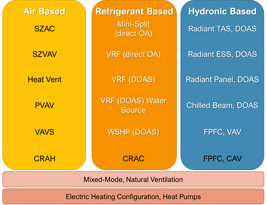
This short list greatly limits energy codes by requiring them to constantly find low energy equivalents inside these existing choices. Equally challenging is federal preemption, which limits certain equipment efficiencies to be governed federal and no state can exceed them. This limits how efficient- some HVAC systems can be and makes this list even more challenging to work with. We recommend an expanded list which can better define a full picture of HVAC systems (click to expand the image on the right).
Building off the same framework of system types defined by their primary fluid of moving heat (air, refrigerant, or water) we end up with this matrix. Across the bottom are two key cross cutting components, mixed-mode systems, or buildings with natural ventilation and the second being electric only configurations or heat pumps. The reason this list is key is that most California commercial buildings implementing all electric solutions are built off these other choices.
Definitions of each is as follows:
| System Type | Title 24 System Title | Description | Detail |
|---|---|---|---|
| Air Based Distribution | System 1 – SZAC | Residential Air Conditioner | Single zone system with constant volume fan, no economizer, DX cooling and furnace |
| Hydronic Based Distribution | System 2 – FPFC | Four Pipe Fan Coils, Constant Volume, DOAS | Central plant with terminal fan coil units with hot water and chilled water coils, with separate ventilation source. Fan coils run at constant volume. |
| Air Based Distribution | System 3 – SZAC | Packaged Single Zone | Single-zone constant volume DX unit with gas heating |
| Air Based Distribution | System 5 – PVAV | Packaged VAV Unit | VAV reheat system; packaged variable volume DX unit with gas heating and with hot water reheat terminal units |
| Air Based Distribution | System 6 – VAVS | Built-up VAV Unit | Variable volume system with chilled water and hot water coils, water-cooled chiller, tower and central boiler |
| Air Based Distribution | System 7 – SZVAV | Packaged Single- Zone VAV Unit | Single-zone variable volume DX unit with variable-speed drive and gas heating |
| System 8 – RESERVED | |||
| Air Based Distribution | System 9 – HEATVENT | Heating and Ventilation Only | Gas heating and ventilation |
| Air Based Distribution | System 10 – CRAH | Computer Room Air Handler | Built-up variable volume unit with chilled water, no heating |
| Refrigerant Based Distribution | System 11 – CRAC | Computer Room Air Conditioner | Packaged variable volume DX unit with no heating |
| Air Based Distribution | System 12 – LAB | Laboratory HVAC System |
Laboratory spaces in a building having a total laboratory design
maximum exhaust rate of 15,000 cfm or less use Table 3, Nonresidential
System Map. Laboratory spaces in a building with building floor area < 150,000 ft2: System 5 – PVAV Laboratory spaces in a building with building floor Area ≥ 150,000 ft2: System 6 – VAVS |
| Air Based Distribution | System 13 – KITCH | Kitchen HVAC System | Dedicated single-zone makeup air unit (MAU) with dedicated exhaust fan. If the building is VAVS per Table 3, the cooling source is chilled water and the heating source is hot water. Otherwise, cooling source is DX and heating source is a gas furnace. |
| Refrigerant Based Distribution | System 14 – MSHP | Mini-Split Heat Pump | Individual refrigerant fan coil units with piped refrigerant to an outdoor compressor, one per zone. Each indoor unit is ducted with outdoor air and includes an air filter locally. |
| Refrigerant Based Distribution | System 15 – VRF_OA | Variable Refrigerant Flow, Ducted Outdoor Air | Zone refrigerant fan coil system with piped refrigerant from variable speed compressors. Each fan coil is ducted with outdoor air and includes an air filter locally. |
| Refrigerant Based Distribution | System 16 – VRF_DOAS | Variable Refrigerant Flow Heat Pump with DOAS | Zone refrigerant fan coil system with piped refrigerant from a shared variable speed multi-headed compressors. Centralized outdoor air tempered, filtered, and provided through a separate path to each zone or zone fan coil. |
| Refrigerant Based Distribution | System 17 – WSVRF_DOAS | Water Source Variable Refrigerant Flow Heat Pump with DOAS | Zone refrigerant fan coil system with piped refrigerant from a multi-headed water source heat pump, one heat pump per floor or set of thermal zones. Heat pump served by condenser water loop with a hot water boiler and fluid cooler. Centralized outdoor air tempered, filtered, and provided to each zone or zone fan coil. |
| Refrigerant Based Distribution | System 18 – WSHP_DOAS | Water Source Heat Pumps, Multi-Speed, DOAS | Central condenser water plant with cooling tower and boiler serving zone water to air heat pump units, one per zone. Units include multi-speed fans. Separate outdoor air tempered, filtered, and provided through a separate dedicated outdoor air unit to each zone or zone fan coil. |
| Hydronic Based Distribution | System 4 – FPFCVAV | Four Pipe Fan Coils, Variable Speed, DOAS | Central plant with variable speed terminal fan units with hot water and chilled water coils, separate outdoor air tempered, filtered and provided through a separate dedicated system. Chilled water plant with hot water boiler plant. |
| Hydronic Based Distribution | System 19 – CHB_DOAS | Chilled Beam, Constant Flow, DOAS | Zone active chilled beam with heating and cooling coils from central air chiller water plant and boiler. Separate dedicated outdoor air system tempers, filters, and controls outdoor air to each chilled beam to induce local airflow. Beams modulate flow of CHW and HW to regulate space temperature. |
| Hydronic Based Distribution | System 20 – RAD_P_DOAS | Radiant Panels, DOAS, Air Cooled Chiller | Zone radiant panels for heating and cooling from central air cooled chiller and boiler. Separate dedicated outdoor air system tempers, filters, and controls outdoor air to each zone. |
| Hydronic Based Distribution | System 21 – RAD_ESS_DOAS | Radiant Embedded Surface System, DOAS | Zone radiant tubes in concrete topping slab for heating and cooling from central air cooled chiller and boiler. Separate dedicated outdoor air system tempers, filters, and controls outdoor air to each zone. |
| Hydronic Based Distribution | System 22 – RAD_TAB_DOAS | Radiant Thermally Active Slab, DOAS | Zone radiant tubes in concrete heavy weight slab for heating and cooling from central air cooled chiller and boiler. Separate dedicated outdoor air system tempers, filters, and controls outdoor air to each zone. |
Tool #2: Expanding Existing Building Codes for Major Renovations
Many existing buildings when they do make upgrades tend to either make lite replacements or undergo a full make over and replace whole systems if not all systems. There are often enhancements which build off integrated design principles for facade enhancements whenever replacing whole HVAC systems, being able to make an old building more insulated and overall reduce the amount of HVAC needed.
The same regulatory process which primarily focuses on new construction today could spend more time finding ways to enhance existing buildings. One key gap to really unlock this potential is a need to identify and categorize an existing building envelope and characteristics. While this may not work for all buildings it could be a pathway for a large portion of buildings, such as schools, retail, or small offices.
Leading efficiency advocates from the Pacific Northwest at the Northwest Energy Efficiency Alliance are already thinking this way with incentive program process; thinking of ways to meet building owners at whatever point they happen to be, and helping them find effective strategies to promote higher efficiency or where possible a whole building retrofit.
Tool #3: Pathway Bridges for Mixed-Fuel Systems
While all electric buildings and HVAC systems do exist today the continued popularity of mixed-fuel systems remain a true thing. Even with the idea of an energy code moving to an all-electric baseline there could be strategies specific to mixed-fuel systems which could help those buildings transition and be future-proof to some degree.
This has already happened in residential code to a certain degree, with requirements for higher voltage availability where laundry equipment is located. In commercial buildings, the same thoughts could be applied. Some systems will ultimately not have any bridge. Constant volume packaged units with furnaces being the main system unable to continue. For others clear opportunities exist. Some ideas might be:
- In mixed air systems, reheat coils being increased in size would allow for heat pumps to one-day use water between 120F and 140F instead of the standard 180F.
- Electrical infrastructure enhancements or conduit for domestic hot water or heating systems.
- Building peak heating loads at or below peak cooling loads to allow for heat pumps to be shared for dual purposes.


